
Gateway Node
The weekend is here and another chance to start poking around with my new RFM69HWs. Here’s my plan. I initially want to get the gateway node connected to a Raspberry PI in my basement via I2C. (I know, there’s probably an easier way, but, hey – I’m doing this for fun and to get better understanding of how I can leverage these boards.) The Pi should be able to poll the gateway periodically to get updated temperature data. I’ll figure out the logging later, by MySQL and a basic graph should give me a good view.
 Connecting the Anarduino Gateway (GW) to the Pi is pretty straight forward. The GW uses 3.3VDC which is available on Pin 1 of the Pi. The I2C pins on the Pi are close by as well on Pin 3 and 5 with a GND pin just down the way at Pin 9. You can see in the image on the right that the 3.3 VIN and GND pins are on the same side as the analog pins; that makes wiring easy. In the following table I’ve laid out the pin mapping between the Anarduino and the Raspberry PI.
[table “T1” not found /]
The heart of the code for the gateway is very compact. Lines 7-9 initialize the board with the defined frequency, network and node ID. These are configured with #define statements. In this case the board is 433 mhz, the networkID is 100 and this node is set as 2.
#define NODEID 2 // GateWay - each node must be unique

#define NETWORKID 100 // Same on all nodes that talk to each other

#define FREQUENCY RF69_433MHZ
[ccN lang=”c”]
void setup() {
Serial.begin(9600);
delay(10);
// RFM69HW setup
Serial.println(“RFM69HW config and setup…”);
radio.initialize(FREQUENCY, NODEID, NETWORKID);
radio.setHighPower(); // only for RFM69HW!
radio.encrypt(null);
Serial.println(“RX at 433 Mhz”);
Serial.print(“GPIO and I2C config and setup…”);
Wire.begin(SLAVE_ADDRESS); // initialize i2c as slave
// define callbacks for i2c communication
Wire.onReceive(receiveData);
Wire.onRequest(sendData);
Serial.println(“\nReady.”);
}
void loop() {
char inData[10];
if (radio.receiveDone())
{
memset(inData, 0, 10);
Serial.print(“#[“);
Serial.print(radio.SENDERID, DEC);
Serial.print(“] “);
for (byte i = 0; i < radio.DATALEN; i++){
Serial.print((char)radio.DATA[i]);
inData[i] = (char)radio.DATA[i];
}
if(inData[0] == 'T')
strcpy(cT, inData);
if(inData[0] == 'B')
strcpy(cB, inData);
Serial.print(" [RX_RSSI:");
Serial.print(radio.RSSI);
Serial.print("]");
if (radio.ACKRequested())
{
byte theNodeID = radio.SENDERID;
radio.sendACK();
Serial.print(" - ACK sent.");
}
Serial.println();
}
}
[/cc]
Lines 30-37 handle data from the remote node. Temperature data is prefixed with 'T' and battery data with 'B'. Both are stored and delivered to the Raspberry Pi on I2C request. Next let's look at the remote node.
Remote (Sensor) Node
Last week I added an antenna to each of the boards. This week I’ll design and build the remote temperature sensor. I selected a SparkFun TMP102 sensor; it’s small, fast and easy to work with. Because the remote node will be running on battery, I also wanted to add the ability to monitor the current battery output so I can (1) know when I need to replace the batteries but also (2) so I can optimize the configuration of the board to maximize battery life.
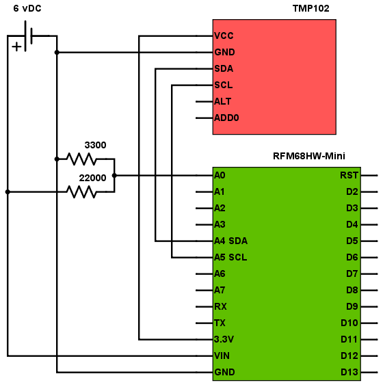
The two resistors act as a voltage divider with the resulting voltage compared to the internal 1.1v reference. Other than that you can see the connections are pretty straight forward with the I2C SDA and SCL pins connected between the sensor and the Anarduino.
Power consumption proved to be an issue as the remote node was rapidly chewing through the battery. I found a library (LowPower.h) that looked pretty good and installed it. SO far I’m seeing good results. Here’s the headers for the node:
Setup if pretty sparse with the reference voltage set to INTERNAL – 1.1v and the RMF69HW is configured. Because I’m not overly concerned about the privacy of temperature data I’ve set encryption off, however it’s nice to have this feature available. The RFM69HW supports a high-power mode which I’m using.